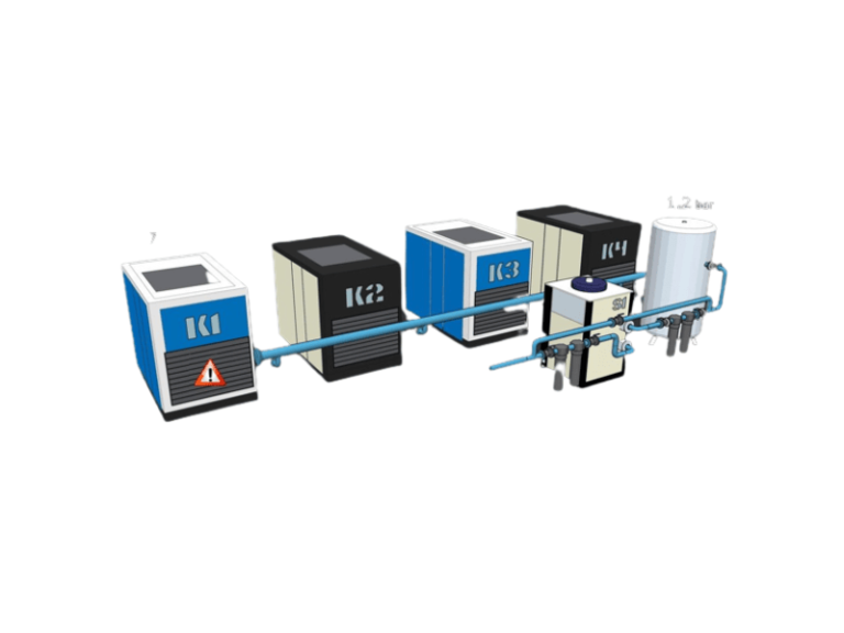
Kompresory Zephyr
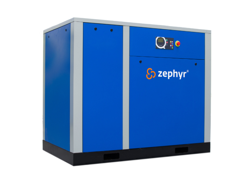
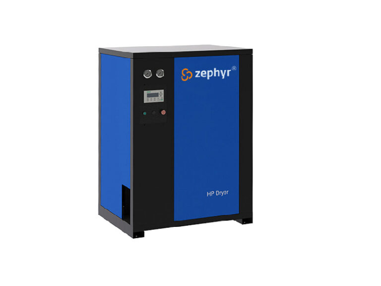
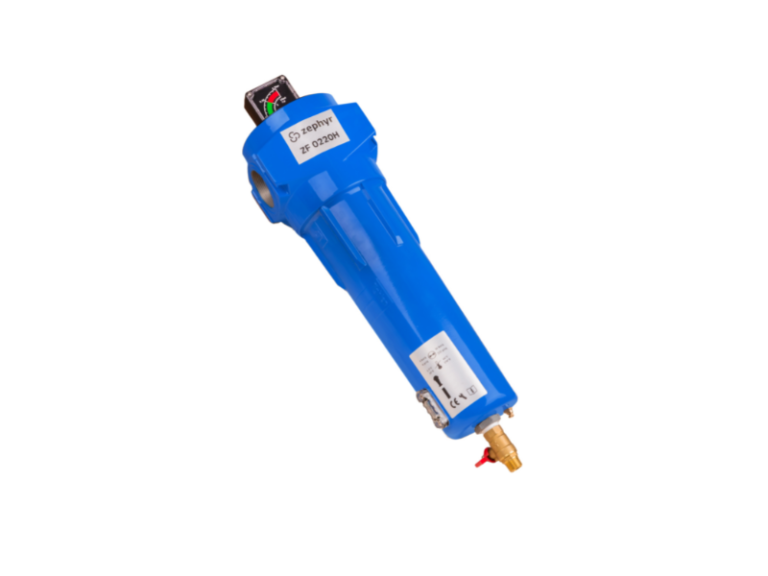
Kompresorová technika značky Zephyr se vyznačuje vynikajícím poměrem cena/výkon.
Značka Zephyr spadala do portfolia švýcarské společností OC Industrial Group, která se věnuje vývoji a projektování technologií v oblasti stlačeného vzduchu. Po dlouholeté spolupráci značku v roce 2022 získala společnost IDEAL-TRADE Service a je jejím výhradním zástupcem v České a Slovenské republice v oblasti prodeje i servisu.
Poskytujeme:
- Prodej kompresorové techniky a příslušenství
- Autorizovaný záruční a pozáruční servis
- Bezplatná servisní linka dostupná 24/7
- Prodej náhradních dílů
Výroba
Výroba a vývoj kompresorové techniky Zephyr jsou realizovány napříč několika kontinenty na výrobní ploše větší než 80 000 metrů čtverečních, a to včetně té nejnáročnější výroby vlastních šroubových elementů. V oblasti bezolejových kompresorů byla již v počátcích výroby zahájena spolupráce s největším německým výrobcem bezolejových šroubových bloků, společností GHH. Tyto kompresory jsou využívány pro technologie určené do aplikací s potřebou 100% bezolejového vzduchu a splňují nejpřísnější normu ISO class 0. Stejně tak byla v roce 2015 zahájena velmi blízká spolupráce s japonským výrobcem spirálových bezolejových bloků, které využívají pro své produkty ti největší světoví výrobci kompresorové techniky.
Vysoká kvalita
Hlavní důraz při samotném vývoji a následné výrobě je kladen na vysokou kvalitu výrobků, nízké servisní náklady a energetickou nenáročnost jejich provozu, tak abychom maximálně snižovali dopady na životní prostředí a celkovou uhlíkovou stopu. I proto se od počátků výroby specializujeme na vývoj vysoce efektivních šroubových elementů EPM, které zajišťují výkon vyšší až o 15 % oproti standardním šroubovým kompresorům, na systémy zpětného získávání tepla při výrobě tlakového vzduchu a pohonů se synchronními motory s permanentními magnety s účinností až 97 % v celém regulačním rozsahu. Samozřejmostí je plnění certifikátů ISO, CE, TÜV, GC a dalších.
Kontaktujte nás
Prodejní tým

Tomáš Jaroš
obchodní manažer (Morava)
Tel.: +420 739 002 168
Email: jaros@itsbrno.cz

Martin Veverka
obchodní manažer SK
Tel.: +421 911 988 899
Email: veverka@itstrencin.sk

Tomáš Purkert
obchodní manažer (Čechy a Praha)
Tel.: +420 730 800 820
Email: purkert@itsbrno.cz

Lukáš Kyselica
obchodní manažer SK (Jižní Slovensko)
Tel.: +421 904 907 139
Email: kyselica@itstrencin.sk

Jiří Svobodník
obchodní manažer (Čechy a Praha)
Tel.: +420 733 617 371
Email: svobodnik@itsbrno.cz
